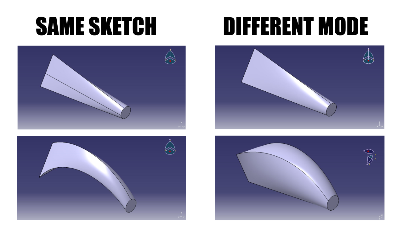
Today, we will learn how to use the Multi section solid command in the Part Design module in CATIA V5. Although a single command, it has a lot of options in it called as – Coupling modes, which at times perplexes the user when and how to use which one. It can be used when a solid has to be generated and has multiple varying sections. Such solid can be generated using spines and guides as well to obtain the desired shape.
Difference between Multi section solid & Padding?

Well, the main difference between both the commands is the cross sections of the solid.
Padding requires just a closed sketch and a direction to be extruded, that’s it. On the other hand, Multi section solid command demands all the sections the solid is going to be comprised of, as well as other constraints like guides, spines and closing points for a complex solid.
To put it simply, padding consists of same cross-section area and profile of the solid body whereas it would differ in multi-section body, as the name suggests!
So lets get started and you will see how each option has its limitation and they could be overcome by their subsequent ones.
Video tutorial down below 👇
Types of Coupling mode –
- Default – Tangency then curvature
- Ratio
- Vertices
- Spine
- Guides
Multi section solid tutorial –
1. Tangency then curvature

This is the default option in the command and there’s nothing complicated. You just have to choose 2 or multiple sections but same profile – like circles or triangles or hexagon of different size, through which the solid is going to pass and that’s it, the job will be done.
2. Ratio

But what about when the profiles are different? That is when you’ll need to go Couplings and choose Ratio instead of Tangency and curvature and then define the profiles to be connected via solid.
3. Vertices

The problem with previous option is that the software forms a solid but chooses a ratio of length of profile on its own on both the sides in order to couple both of them. This gives rise to unwanted and unequal surfaces to be formed.
So to tackle this problem, what you can do is ensure that there are equal no. of sides/vertices on both profiles. Choose Vertices in dropdown menu as coupling mode. This way, the software knows that it has to connect the 1st vertex to corresponding 1st vertex on other profile and same with other vertices. For eg. In our case, we have a triangle as 1st section and Circle as the 2nd section so we will divide the circle in 3 equal parts.
4. Spine

If your solid object consisting of various sections needs to be bent rather than straight, then this is an add on! Keep all settings same as above. Go to Generative shape design and draw a curve from 1 vertex to other and select this as Spine in Spine option in Multi section solid dialog box.
5. Guides

The last variant and the one which gives you the most flexibility is again an add on. Keep same settings as in Vertices and now instead of drawing 1 curve from 1 vertex to another, draw multiple of such curves/straight lines and connect all of the vertices. After that, choose Guides from dialog box and select all the curves as these guides and bam! In this way, you can create even most the complex shapes easily!
Here’s a detailed video tutorial which I think would be easier for you to follow
Similarly, you can use the same above methods to generate multi section surfaces instead of solid objects. Along with that, you can also remove multi section solids through a solid by similar tricks 😉
You may find interesting – How to import airfoil co-ordinates in CATIA V5?
Please let me know in the comment section below if you face any kind of difficulties 🙂

