No matter what 3D modeling software you use there comes a time when you need to import points because of the complexity of a part or a curve.
And at times when you are new to the software or a beginner, you need help. So this article is for them who are in their rudimentary stages of software and need help on how to import airfoil coordinates from Excel to CATIA V5.
Procedure to import airfoil coordinates from Excel to CATIA –
1. Get the coordinates of curve
First, you need an Excel file in which you have all the coordinates of the curve or an airfoil.
If you want to plot an airfoil, then just head over to NACA website and download the coordinate file of the airfoil you require.
2. Download the GSDpointsplineloftfromExcel.xls file
Now here’s a file you need to download named – GenerativeShapeDesign_SplineFromExcel.xls
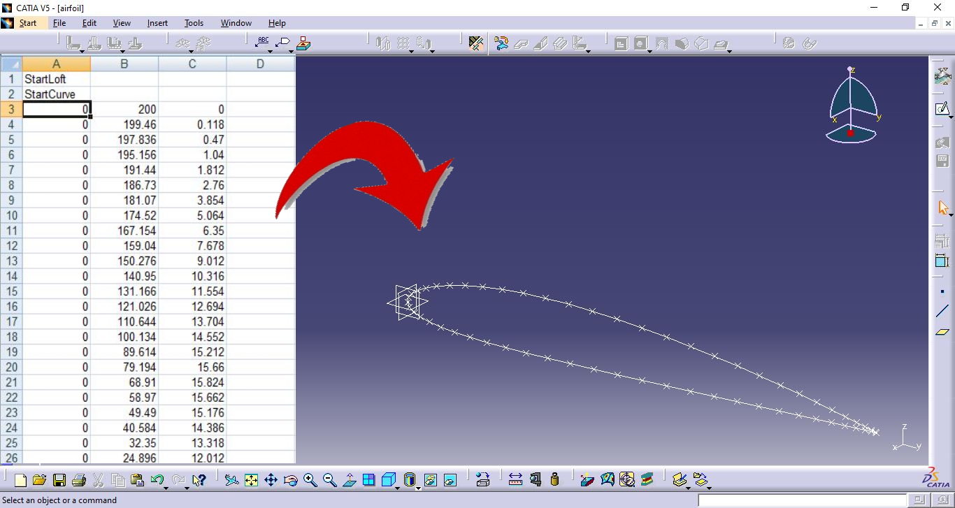
The first column consists of all X coordinates, 2nd column consists of all the Y coordinates and the 3rd all Z coordinates in this file. Copy the coordinates of the airfoil into this file as shown below.

3. Enable Macros
If Excel is warning you that “Macros is disabled”, then enable it.

4. Go to View, Macros then View Macros

5. Select parameters and Run
Select Feuil1.main from the dropdown menu and the current Excel file.
Click on Run. If you just need to plot points, type “1” and press Enter.
If you need to plot the curve or eventually going to connect them and form a sketch then type “1” and press Enter and voila, there you go.

After you complete the sketch you can now transform the airfoil into a wing by pad or shell command available in the Body part design 😀
Here’s a video tutorial which will make things more clear for you –