Every designer or CAE engineer, sooner or later comes across a point where the design of a component or a part is so complex that he indeed has no other option rather than importing the 2D co-ordinates of the curves and then work on it. I did too. And so today we will learn how to import coordinates into ANSYS Workbench. You can then extrude or surface it in Design Modeler or Spaceclaim.
VIDEO TUTORIAL down below 😉
Here, today, we will see how to import airfoil coordinates because airfoils can have easy(NACA 0012) as well as immensely complex shapes. And also because airfoil is quite an area of interest for many beginners and amateurs out there. So let’s begin
Steps to import coordinates into ANSYS
1. Download coordinates from NACA

- For this airfoil tutorial specially, we are going to go for NACA 2412.
- Head over to the NACA website, search 2412.
- Click on “Send to airfoil plotter”
- Click on “save file as .csv file” i.e MS Excel compatible file.
2. Make ANSYS compatible file

- Now, the thing is, ANSYS accepts a coordinate file only if its .txt file. Not only that but it has a specific format.
- The format is as follows –
- 1st column – All 1’s
- 2nd column – Serial numbers
- 3rd, 4th & 5th column – X, Y & Z coordinates respectively (NOTE – All X, Y & Z coordinates should have equal decimal places)
- When all done, copy all the 5 columns to Notepad & Save it. We have now made an ANSYS compatible file which it can read & thus plot the points.
3. Import coordinate file in ANSYS
- Open DesignModeler.
- In the Menu bar at the top, click on “Points”
- After clicking on Points, you can see 2 options –
- From coordinate file
- insert manually
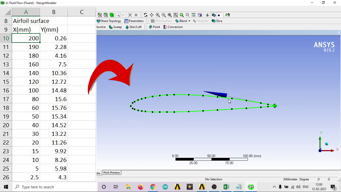
- Choose “import file” and choose your notepad file which we saved.
- Click on Generate and DONE!
That’s it, easy, right? You bet it is. Well, I will it make it easier. Here’s a video tutorial on how to import airfoil coordinates to ANSYS
You might wanna learn how to import coordinates in CATIA V5?
Hope you found it helpful. Comment down below if you face any difficulties 😉 I’ll get back to them ASAP