In my earlier tutorial, you learned how to import coordinates into CATIA V5 from Excel with the help of Macros. In this tutorial, we will see how to use one of the most important and popular command – Multi section solid, in CATIA and explore different options & modes of coupling in it.
The main difference between padding OR extrusion command and multi section solid is that – padding is used when the profile and cross section remains the same throughout whereas either one of them or both change in multi section solid.
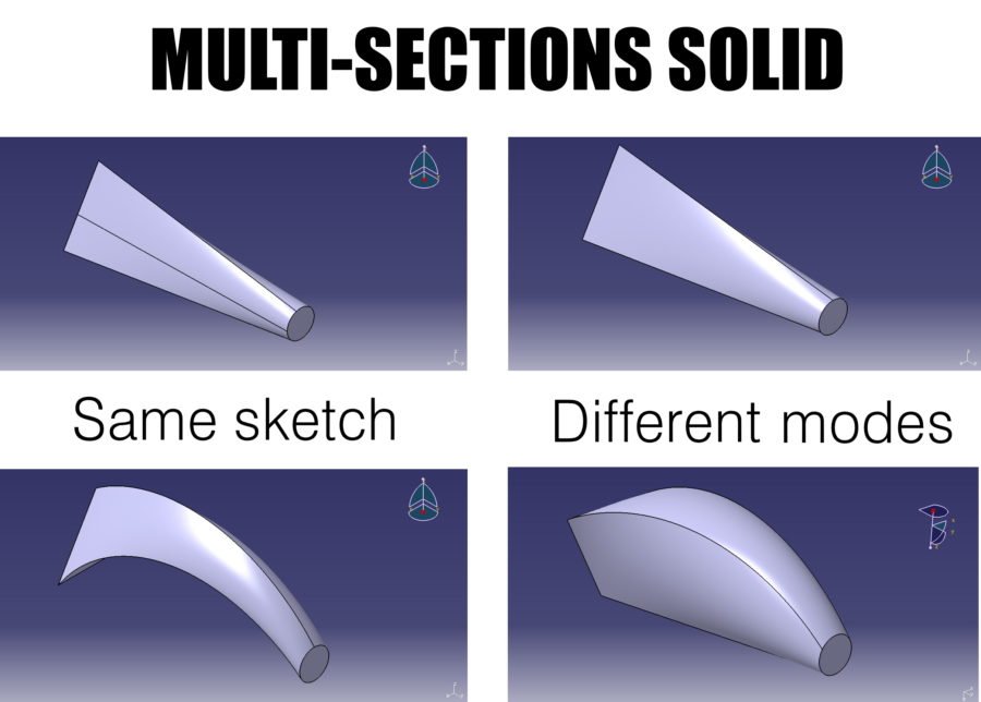
So here, for our example and simplicity we will consider a circular section and a triangular section.
Keeping the sections same, we will explore how different coupling modes and options change the output result.
And ohh.. don’t forget, I have a video tutorial at the end. Do watch it! It will make things easier for you.
Modes of coupling in Multi section solid –
1. Ratio mode

When both the sections don’t have equal number of vertices, then this mode is to be used. In our case, circle has NO vertices while triangle has 3. So by selecting both the sections and ratio mode in dropdown coupling mode, one can make a solid containing multiple sections.
2. Vertices mode

In ratio mode, as you can see, the sections have coupled but there are unequal number of edges and surfaces (there should be 3, since 3 edges of triangle but have been generated). So first divide the circle into 3 equal parts by going into sketcher then select both the sections choosing the coupling mode as Vertices. Now you have smoother connections between both sections and equal edges.
3. Spine

The multi section solid command assumes a straight path of extrusion when the 2 profiles are selected. To give it a bend, draw a curve joining the 2 sections from any vertex-to-vertex. Now after selecting 2 profiles, choose Spine and select the new line you created. Here’s the result..
4. Using Guide

Guide option gives you the maximum flexibility in multi section solid command. Just like you drew spine, draw multiple lines from each vertex. This way you can create any shape by keeping the same sections and just manipulating the lines. Select these lines as guide curves and there you go!
Here’s a video tutorial as promised 😀 –